
Zinc Air Fuel Cell Test System
The Challenge:
Develop an application capable of exercising multiple Zinc Air Fuel Cells (ZAFC’s) while monitoring their performance and logging all monitored process variables.

Figure 1. The performance and characteristics of multiple Zinc Air Fuel Cells running prolonged tests are made possible using LabVIEW, the LabVIEW State Diagram Editor and NI-VISA
The Solution:
The LabVIEW State Diagram Editor was used to develop the structure of a LV 8.2 application that made use of set of reentrant drivers developed to control the Amrel loads that provided virtual loads required to test the fuel cells. Both automatic and manual mode of operation were required to allow the users to test new products and design and to allow for customized scheduling of load changes to simulated prolonged use.

Figure 2. Project specifications indicated that the ZAFC’s required a Manual Mode and an Automatic Mode of operation. The application allowed the user to transition between these states at will.
Abstract:
During the design phase of the application, it was determined that each fuel cell had to be tested and monitored independently of any other testing that may be taking place. It was also determined at design time that all of the functionality present in the Manual mode of operation was required in the automatic mode. Another detail that required special attention was that all of the electronic loads shared a single GPIB port as the communication medium.
NI-VISA and NI-Spy Allow for Easy Driver Development
NI-VISA was used to develop the interface drivers. The use of NI-VISA allowed for multiple communications sessions to be active at the same time. NI-VISA’s tight coupling with NI-Spy allowed monitoring of the GPIB interactions during the initial testing and debugging of the drivers.

Figure 3. The NI-Spy utility allows for the monitoring and logging of the communication details of NI-VISA.
Once the details of the communications and functionality were tested and benchmarked, they were converted to re-entrant VI’s to permit multiple ZAFC to be tested at the same without interaction between the controlling processes that will be directing the testing.
Manual Mode Code Development
Since all of the functionality required in Manual Mode was required also required in Automatic mode, the Manual mode of operation was developed and tested first. This approach allowed the common functionality to be tested and benchmarked and refined once for both modes.
In the Manual Mode of operation, the application will first determine if the Amrel load is available and operational (Init). If the preliminary check of the load failed an error flag will be set (in Set Init Error) and a graceful shutdown will be initiated (Shutdown). If the initial checks showed no errors, the Manual Mode of operation will periodically transition between the “What commands?” state and the “Time to Read?” states.
The “What commands” state will determine if a command was issued by the GUI process and if will cause a transition to the appropriate state (“Set output”, “Set Current”, or “Set Shutdown”) if a command was received. When no command is received the “Time to Read?” state will be entered to determine if the state of the loads voltage or current should be updated. Once the “Manual Mode” of operations was tested and found acceptable, the Automatic Mode of operation was developed starting with a clone of the Manual Mode.
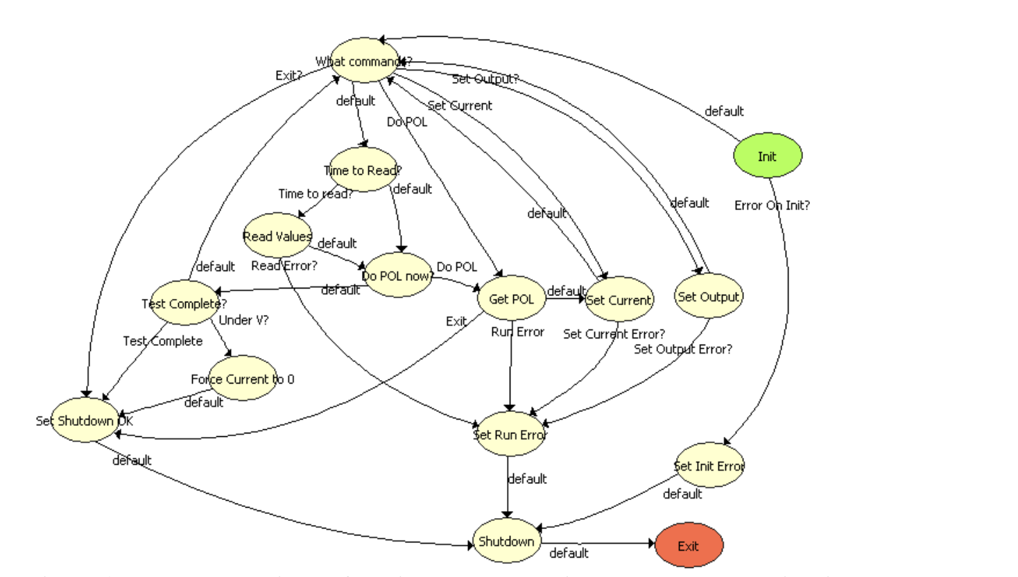
Figure 5. Auto mode. The automatic mode of operation was developed by using the Manual Mode as a starting point and additional states were added to support the automated schedule and to detect test end conditions.
Automatic Mode is an Embellished Form of the Manual Mode
A careful comparison of the state diagram used for the Manual mode of operation (Figure 4) and the state diagram for the Automatic mode will show that they share the same mechanisms for starting, handling user requests, error recovery and shutdown. The new states (“Do POL Now?”, “Get POL”, and “Test Complete?” along with their ancillary states) implement the scheduling and checks required to properly exercise the ZAFC and determine when the ZAFC has reached the end of its life.
Summary
LabVIEW along with the NI-VISA, NI-Spy and the NI LabVIEW State Diagram Toolkit made the development of the “Zinc Air Fuel Cell Test System” both fun and easy. Once one station was completed, the application was cloned to allow multiple ZAFC to be tested 24 X 7. NI-Spy made it easy to develop the driver. The State Diagram Toolkit permitted the development of a self-documented application that was readily converted for other use.
Industry:
Prototype TestAttributions:
Timothy D. Nolan, Engineer, Measurement & Automation
Data Science Automation, Inc. USA
Benjamin A. Rayner, Architect, Measurement & Automation
Data Science Automation, Inc. USA
Products Used:
LabVIEW 8.2
NI VISA 4.0
NI LabVIEW State Diagram Toolkit 1.0
Self-Qualification Form
As a technical user, you may know exactly what you need from us already. If you do, save time and streamline the discovery process with our self-qualification form, where you can let DSA know exactly what you need.
