
Enhanced Maintainability and Reliability Through Software Backplanes
The Challenge
Develop a replacement for an existing DOS-based application that is suffering from poor reliability and worse maintainability. The upgrade would improve the user interface while maintaining backwards use-compatibility with the previous version. Additionally, the software requires an expandable framework to support the incorporation of new, unforeseen types of testing.
The Solution
Taking advantage of LabVIEW’s advanced architectural features, Data Science Automation (DSA) created software backplanes for the user interface and the test engine that support software plugin modules. The new user interface supports operations via hot-keys, menus and on-screen buttons. The data management requirements were met through an integrated Oracle database.
Abstract
A manufacturer of industrial and mil-spec circuit breakers needs to test the mechanical operation of their products before final assembly and shipment. An existing system performed the necessary testing but suffered from poor reliability and, due to the age of the equipment, even poorer maintainability. The answer to their problems was a system that improved the existing user interface, and enhanced maintainability and reliability through a modular software architecture. Hardware Structure
The application’s hardware consists of hardware for positioning the breaker handle, raising and lowering the contactors used for the millivolt-drop test, and lifting the contactor arm to measure contact force. To tie all this I/O together the system incorporates a PXI-8196 controller housed in a PXI-1042 chassis. Keeping the controller company in the chassis is a PXI 6221 M-Series DAQ card, a PXI-6528 24-bit Industrial Digital I/O card, and a PXI-7342 2-Axis Stepper/Servo Motion Controller card.
The PXI-6221 measures the millivolt drop across the contacts, the contact closure force and contact position with an LVDT. The PXI-6528 drives solenoids that control the pneumatic motion system responsible for positioning the circuit breaker handle. The PXI-7342 interacts with the servo motors that lift the closed contacts and raise the millivolt drop measurement contactors.
For interconnecting the cards to the I/O, the system utilizes a SCC-68 for the analog I/O, and an SCB-100 for digital signals. It leverages the slots in the SCC-68 to house SCC-SG24 and SCC-SG11 modules for conditioning and calibrating the contact force strain-gage input, respectively.
Twin Software Backplanes
Although the application appears to the user as a single monolithic application, it actually consists of two independent processes. The one visible to the operator is the Main Interface. The other process is the Background Test Engine, and as its name implies, it is a background process that oversees the actual test process. Each of these processes implements a software backplane that supports the creation of application-specific plugin modules – or the reuse of existing standard test plugins and display screens.
Main Interface
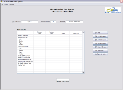
The VI forming the user interface is architected as a generic application that has the job of dynamically calling and displaying interface screens. It also provides several standard resources for use by the interface screens. The first of these resources is a subpanel. Thanks to this display object, the Main Interface when running appears to offer a wide variety of interface features, whereas, in fact, it provides nearly none. Rather, nearly all the display and control functionality resides in the plugin display screens (Figure 1).
Figure 1 – Although it appears that the user interface for the application sports a variety of different controls and indicators, appearances can be deceiving. In fact, the main interface itself provides nearly no control inputs. Rather, a plugin VI inserted into a subpanel provides nearly all the user interface’s controls. This plugin structure simplifies development by giving the developer a well-defined interface for creating the desired user interface.
When a display screen is selected, the code starts by passing to it a reference to the Main Interface VI (this gives the access to mouse, key and menu events generated in the Main Interface), a reference to the Main Interface’s menubar (so if needed the plugin screen can create its own menus) and two user events created in the Main Interface. The first of these events is a global shutdown event that will bring the system to a safe halt. The second event, when fired, causes the display screen to change. After this data is passed to the screen, the code uses the VI reference used to launch the plugin to insert it into the subpanel. To improve performance, and decrease the time required to change screens, the code buffers all screen VI references.
The primary display screen for this application is the test progress screen which implements a multi-mode user interface. The goal is a user interface that serves two very different user demographics. First are new operators. Because they have limited experience with the old system they want the most efficient user interface possible. The second group of users that the software addresses is operators that have a decade or more using the old system. For these users the goal is to minimize retraining costs by providing a use experience that mimics the operation of the old system.
To meet these requirements the interface was design to support three main methods of interaction: 1) pull-down menus, 2) functions keys, and 3) on-screen buttons. Note that options 2 and 3 implement the logic for emulating the user interactions of the old system.
The overall structure of the test progress screen is event-driven. Operationally, a test should begin when a circuit breaker is inserted into the test fixture and the door interlock is closed. To implement this functionality, when the Test Progress screen launches, it registers a DAQ Signal Change Detection Event. However this event is initially disabled by passing to it a null DAQmx task reference. Inside the screen’s main event loop is an event that determines whether or not the setup data that the operator has selected defines a valid test. When this event determines that the test setups are valid, it creates a DAQmx task with Change Detection timing tied to the input monitoring the state of the door interlock switch, and passes the resulting task reference to the DAQ Event created earlier.
At this point the DAQ event will trigger when the door switch changes states. When this change occurs, the code verifies that the door is closing, and if it is checks to verify that a circuit breaker is present. If this check is also successful, the code triggers a test start by passing the test setup data to the background test engine, clears the DAQmx task, and disables the DAQ event.
Background Test Engine
Conceptually the software backplane implemented in the Background Test Engine holds several things in common with the Main Interface – not the least of which is goal of being a generic execution environment for application-specific code. A key aspect of this structure is that the decision of which test plugin to be executed next occurs in the plugin that is executing now. Hence the test sequence logic is hidden from the test engine, thus eliminating the possibility that a change in the logic will break the test engine. In addition, to protect the test engine from changes in the structure of the test data, this value is passed between test plugins as a variant (Figure 2).
Figure 2 – Demonstrating the concept of Information Hiding, this VI Server-based plugin architecture hides the specifics of how a test is performed from the logic that is responsible for calling the plugin VIs that implement the test process. Note for example the variant value that is used to pass data between plugin modules as they are called.

Each test plugin implements one test and has the basic structure of a state machine built inside the timeout event of an event structure. This combination functionality allows the test to run unimpeded, but with the ability to be interrupted very quickly in the event of a test abort or emergency shutdown.
Industry:
Production ATEAttributions:
Richard M. BrueggmanFounder, President, & CEO
Data Science Automation, Inc.
USA
and
Michael L. Porter
Architect, Measurement & Automation
Data Science Automation, Inc.
USA
and
Ryan W. Vallieu
Consultant, Measurement & Automation
Data Science Automation, Inc.
USA
Products Used:
LabVIEW 8.2.1
PXI-1031 4-Slot PXI Chassis
PXI-8196 PXI Controller
PXI-1042
PXI-6221 M-Series DAQ Card
PXI-6528 Industrial DIO Card
PXI-7342 2-Axis Stepper/Servo Motion Controller
SCC-68
SCB-100
SCC-SG24
SCC-SG11
SH100-100-F Shielded Cable
SC68-C68-S Shielded Cable
UMI-7764
28 DIO Channels for system status/control
ELO 1915L Touch Screen Monitor
Sorensen DCS 8-125E 100 Amp Power Supply with GPIB Control option
Applied Motion Products BLuAC5-S Servo Drives
Applied Motion Products VL23 Servo Motors
Schaevitz LBB375PA-100 LVDT Gauge
SchaevitzLDM-1000 LVDT Conditioner Module
Interface Load Cells SM-100 and SM-250
CR Magnetics CR5410S-30 Current Transducer
Bimba CFO-06550-A 4-Position Pneumatic Cylinder
Zebra Printer
Self-Qualification Form
As a technical user, you may know exactly what you need from us already. If you do, save time and streamline the discovery process with our self-qualification form, where you can let DSA know exactly what you need.
