
Mercury Emissions Stack Monitor
The Challenge:
Developing a reliable mercury emissions sampling system to provide the control, calibration and maintenance features required by stringent Federal regulations for coal fired power plants.

Figure 1. Typical coal fired power plant emissions stacks.
The Solution:
Creating a flexible, real time software architecture deployed to a Compact FieldPoint (CFP) Programmable Automation Controller (PAC) with a wireless communications interface to a PDA. The PDA provides all status display and operator interaction. The system saves data to the CompactFlash drive, and broadcasts data over an RS-485 serial connection to a data logger.
Abstract:
In order to comply with Federal Clean Air regulations, mercury emissions from coal-fired power plants (Figure 1). must be continuously monitored. The proportional measurement technique requires sampling rates to be continuously adjusted to remain in proportion with stack flow. In addition, all calibration, maintenance and leak checking modes must be automated. The system uses a Programmable Automation Controller (PAC) that operates remotely, controlling the sample collection for as much as a week. The only computer connection is an RS-485 output line to a data logger. Therefore, all control and programming of the PAC, as well as all user feedback, is through a wireless connection to a PDA, running National Instruments LabVIEW PDA module (Figure 2).
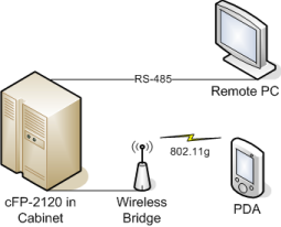
Figure 2. System network architecture.
Sampling Mode
The full system controlled two sampling paths consisting of sampling pumps, leak check valves and proportional control
valves operated through the pulse-width modulation cFP module. Immediately after connecting the Compact FieldPoint bank, we were able to test and troubleshoot all the hardware modules in the system. This allowed several design issues to be addressed very early in process, before the LabVIEW programming had become too specific.
Data was to be collected at one-second intervals, with each collection of data broadcast over a serial connection to a remote system. The data was also averaged hourly, and these hourly averages were saved to non-volatile memory, as well as being used to adjust set points for flow and temperature control. All data was also compared with a series of alarm set points that would raise system flags or stop sampling during the alarm. The system needed to have the ability to enter and return from a suspended function during an alarm. The integrated RS-485 connection on the cFP-2120 allowed industrial serial communication, and the expanded memory of the CompactFlash slot enabled long-tem data storage for the system.
Running simultaneously with the data collection, broadcasting and analysis were the control loops. A set of heaters were controlled by PID loops to maintain the sampling ports at constant temperature. Also, each flow path was controlled by its own PID controller in order to maintain the sampling flow at a constant ratio to changing stack flow rate. Each of these loops referenced user-defined set points in conjunction with measured values to maintain the flow and temperature at required values.
PDA Connection
The remote location of the system, and lack of network connected meant that the device would run ‘headless’ with no computer connection. The deployed executable communicated with a rugged PDA through a shared variable library, with the cFP-2120 as the shared variable server. The variables were network published, and an 802.11 wireless ethernet bridge connected to the cFP-2120 ethernet port to the wireless capability of the PDA. Both system commands and changes of program state were communicated through the PDA, which could also display and change system settings. Other than beginning the automated sampling mode described above, the PDA was used to operate several user-interactive modes.
Calibration
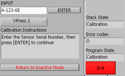
This mode would check all the built-in sensors of the system. The calibrations ranges in complexity from a simple comparison to standard in the thermocouple calibration, to an intricate, controlled-flow check of the Dry Gas Meters. All calibration data was stored locally on the PAC in LabVIEW configuration file format, as a .CAL file. The most recent calibration values were retrieved from these files in order to convert and scale raw values read from the FieldPoint module in each sampling run. This is an example of a user input screen, where data is sent to the FieldPoint from the user.
PDA calibration screen, for user input
Leak Check:
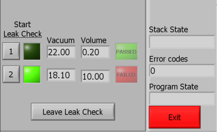
This was another automated check of the system used before each sampling run, used to verify the integrity of the sample path. The values were checked before and after each test, and the user could interact with the device to accept or repeat tests as necessary. This is an example of a user controlling system functions with the PDA, as the user only had press a button to begin a test, which was automated and repeatable.
PDA leak check screen, for system and automation control
Maintenance:
During maintenance mode, the user had full control of the system. This mode could turn on and off all pumps and valves, as well as read the current state or level of all the FieldPoint channels. In the mode, the user-defined functional set points could be entered, read or updated. During this mode the cFP-2120 system time would be automatically synchronized with the PDA to prevent divergence of timestamp values.
Data Transfer:
The two GB memory of the CompactFlash memory meant that several years of data could be accumulated on the system. For diagnostic procedures and record keeping, a transfer mechanism was set up to collect data files from the PAC to the PDA. The PDA would connect to the Compact FieldPoint, which would then populate a list with all the existing .DAT or .CAL files, any of which could be selected and copied through TCP protocol to local memory. The system also prevented currently used and unfinished data files from being transferred in the middle of a sampling run.
Summary
The success of the project was due to the processing and automation power of the cFP-2120, as well as the customer ease of use that derived from integrating the PDA control system. This streamlined the interface for the user, while allowing the automated processes to take care of most of the sampling functions. Speed was also enhanced by the cFP-2120 incorporating Ethernet and serial communication, as well as expandable memory, which saved time by avoiding excess hardware integration and troubleshooting.
Industry:
ControlAttributions:
Timothy Nolan
Engineer, Measurement & Automation
Data Science Automation, Inc.
USA
Products Used:
cFP-2120
cFP-TC-120
cFP-AI-110
cFP-DI-330
cFP-DO-410
cFP-QUAD-510
cFP-PWM-520
LabVIEW 8.20
LabVIEW Realtime 8.20
LabVIEW PDA Module 8.20
Self-Qualification Form
As a technical user, you may know exactly what you need from us already. If you do, save time and streamline the discovery process with our self-qualification form, where you can let DSA know exactly what you need.
