
Contact Resistance Measurement System
The Challenge
Design an automated system to measure contact resistance between a probe and flat coupon capable of regulating the force between them and dragging the probe across the coupon. Simultaneously record images from four cameras and place all data into an easily mineable database.
The Solution
NI hardware was used for load cell conditioning, image acquisition, pressure regulation, motion control, and GPIB control of electrical measurement instruments and a single LabVIEW application was created, capable of positioning the probe above the coupon, increasing force, dragging, and decreasing force, all while performing electrical measurements and recording images.
Introduction
Data Science Automation (DSA) is the premier National Instruments Alliance Partner. DSA integrates commercial off-the-shelf (COTS) components from automation technology vendors to create custom, adaptive automation solutions for a diversity of research, manufacturing, government and business operations to:
∙ acquire, analyze, present and manage data
∙ design, simulate, test and validate products
∙ monitor, predict, control and optimize processes
∙ invent, draft, prototype and build machines
for maximum productivity, quality, profit and understanding.
DSA is a certified member of the Control Systems Integrators Association (CSIA) and staffs multiple National Instruments Certified Training Centers with more certified LabVIEW Architects than other integrators.
Our client is a manufacturer of electronic components and therefore contact resistance measurements are a critical part of their product development. Their primary means of making these measurements was a legacy system not upgradeable with currently available technology, and thus represented a significant risk in case of system failure. They selected DSA because of our responsiveness, depth of understanding of complex engineered systems and insight into their process and expectations. They felt that DSA’s adaptive solution would compound their investment.
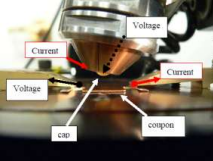
Figure 1. Contact resistance measurement setup
Approach
The main purpose of the contact resistance measurement system is to precisely control, in an automated series of steps, the position of a spherical probe relative to a flat coupon (shown in Figure 1), regulate the physical force between the two, and perform resistance measurements between them. The test steps (some optional) include performing a light initial touch between probe and coupon, increasing the load at a specified rate and intervals, wiping the probe across the coupon, unloading, and pulling the probe off of the coupon if any cold welding has occurred. Resistance measurements are made at specified intervals during loading, wiping, and unloading, while images are simultaneously recorded from four digital cameras for visual inspection.
To accomplish this, the system requires interaction with several hardware components which NI hardware and software were used to integrate:
∙ A Keithley 2182A Nanovoltmeter and 2400 SourceMeter® are used to perform the low-voltage measurements required for contact resistance measurements. They are controlled via an NI PCI-GPIB and a combination of NI-certified drivers and custom code provided by Keithley.
∙ The probe head is positioned relative to the stationary coupon with a Galil 3-axis motion controller. The system is controlled via Ethernet with a driver package written by DSA. ∙ A load arm applies the force between the cap and coupon (with the Z-stage being used for gross positioning only). It is pre-loaded to provide tension for situations where the probe must be pulled off the coupon. Force is applied via compressed air using a Proportion-Air pressure regulator and piston/cylinder, with feedback provided by a load cell. The pressure regulator is controlled using the analog outputs of an NI6323, and the load cells are conditioned using an NI cDAQ-9171 and NI 9237.
∙ The probe is also rotated to expose unused surfaces to the coupon for repeated tests. This is accomplished using an Oriental motor stepping motor and controller via serial interface. A driver package written by DSA using VISA functions is used to interact with this hardware.
∙ Four Basler GigE cameras are used to capture images from various angles using an NI PCIe 8235 and the NI IMAQdx driver.
.png?width=466&height=368&name=unnamed%20(79).png)
Figure 2. Main user interface
Figure 2 shows the primary user interface. The user may enter metadata (TEST, PROBE, FLAT) and test parameters on the left. The Status window displays software messages, and the two graphs display data as it is acquired. The controls in the upper left are used for manual positioning and control/calibration of the pressure regulator and load cell. These controls are all locked out when an actual test is running.
Figure 3. Camera window

A second monitor contains another front panel window shown in Figure 3. This provides the user with a live display from all four cameras as well as additional motion and data acquisition controls to use in manual mode.
One of the main challenges in developing this application was selecting an architecture that could simultaneously manage interactions with all of the hardware components as well as handshaking between software modules. The solution was to take advantage of the versatility of software generated user events. Each piece of hardware has a corresponding software module, and there are additional software-only modules. Each is a state machine containing an event structure registered to user events corresponding to that module, which are stored in functional global variables. The modules therefore operate independently and may freely interact, allowing for a high degree of scalability.
For example, when a test is run, a request is sent to a recipe handling module. The front panel then continues to update while the recipe handler executes the program independently. The front panel and recipe handler may send requests to other software modules at the same time but those modules will handle them in the order received. The recipe handler sends requests for position/load changes and electrical measurements to the appropriate modules, and receives back data that is routed to a data handling module which saves data to file. Some further examples of this modularity:
∙ The module controlling the camera is used both as a front panel display and for recording images. It normally updates a live display of all four cameras, but when it receives a request or record images, it creates IMAQ copies and passes them to another module for saving.
∙ The two graphs and the status window on the front panel have corresponding software modules so that other modules may update the displays without interruption. And, since the modules display data in the order it is received (via user events) the data remains organized.
∙ The pressure regulator requires continuous, tuned feedback from the load cell for its closed loop control. This function is handled by a separate module so there are no interruptions that could lead to instability.
∙ Sets of 4 recorded images need to be stitched together into single images and descriptive text needs to be added. This process is relatively resource-intensive but as it occurs in an independent module the system can allocate resources as necessary while allowing other modules run.
The recipe handler uses a text-based command set and by default builds a set of instructions automatically based on the information entered on the front panel. But, the user may also choose to load a custom set of instructions from a text file, which is why a human-readable command set is used. Data are stored in TDMS file which are mineable using DIAdem. All of the metadata fields shown on the front panel may be used as filters, which is important to the customer because they generate large databases of resistance measurements.
The customer now has a modern replacement for a legacy system that created increased risk as it aged. LabVIEW hardware and software, along with third party components, have been integrated into a modular and scalable contact resistance measurement system. The customer also plans to implement specialized geometric arrangements in the future, and a text-based command set gives them the ability to create completely customized test instructions. They have also received formal LabVIEW training, giving them the ability to further customize the code as the instrument is exercised. For example, the messages in the status window may be customized by simply inserting requests to post messages anywhere the user desires. Overall, National Instruments products and services have allowed Data Science Automation to integrate several measurement and control systems into a single integrated testing unit. Additionally, during the development phase the customer decided to switch from a third-party load cell conditioner to the NI-9237 which allowed for better integration. NI phone support was a valuable resource during the entire development cycle, including during customer visits when time was at a premium. Our customer now possesses a modern contact resistance measurement system which may be duplicated in the future as the demands for testing increase.
Contact Information
Paul R. Tortora, 724-942-6330, www.DSAutomation.comIndustry:
Automated TestAttributions:
Paul Tortora, Ph.D., Senior Engineer, Data Science Automation
Quintin R. Stotts, Senior Measurement & Automation Consultant, Data Science Automation
Products Used:
NI LabVIEW 2010
NI DIAdem 2011
NI PCI-GPIB
NI PCIe-6323
NI PCIe-8235
NI cDAQ-9171
NI 9237
Self-Qualification Form
As a technical user, you may know exactly what you need from us already. If you do, save time and streamline the discovery process with our self-qualification form, where you can let DSA know exactly what you need.
