
FPGA Interfacing with Sonotec SONOCHECK Bubble Detector
The Challenge
Determining the presence of bubbles in fluids in the tubing of a biomedical device in order to provide patient protection.
The Solution
Interfacing with the SONOCHECK bubble detector with its 1 KHz PWM output mode was accomplished through use of the RMC DIO channels and provided the safest and most reliable implementation.
Introduction
Data Science Automation (DSA) is a premier National Instruments (NI) Alliance Partner that specializes in automating and educating the world leading companies. Clients choose DSA because of DSA’s deep knowledge of National Instruments products, disciplined process of developing adaptive project solutions, staff of skilled Certified LabVIEW Architects and Certified Professional Instructors, and unique focus on empowerment through education and co-development.
The fluid system in a biomedical device had to be free of bubbles for patient protection. Prior solutions implemented were making use of the serial capability of the device and did not meet requirements for speed and risk mitigation. The DIO on the sbRIO were considered to be part of the instrument hardware by the regulatory committee and thus utilizing the PWM output mode of the SONOCHECK Bubble Detector was considered the most reliable, repeatable, and provided the fastest detection with the 40 MHz clock allowing for accurate measurement of 1 cycle of the 1000 Hz PWM output from the device.
In addition to the standard operating mode with the FPGA being used to measure the PWM output of the Bubble Detector it also had to interface with the device and run the self-test protocol handshaking with digital output and input lines from the Bubble Detector. Being able to run the PWM input and characterization in true parallel with the control logic functions for the Bubble Detector simplified implementation and made time-to-market faster as well.
Self-Test Logic
A main state machine on the FPGA controlled the enabled state of the bubble detector, with transitions from not enabled to enabled state initiating a self-test of the detector. The self-test is performed by a state machine. In order to perform the self-test a digital output line tied to the Bubble Detector “Test”
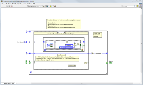
input line is set to a true Boolean level in the first state machine state. In the main self-testing state the bubble detection reported by the Bubble Detector PWM input loop is monitored. This state is maintained and a 1-ms loop timed while loop is allowed to count down for up to 500-ms or until the PWM loop reports a Bubble detection via an FPGA Global set by the PWM Bubble Detector measurement loop. Once the self-test is complete the “Test” output line is set to a false Boolean level. The self-test state machine then waits for up to 500 ms for the PWM Bubble Detector logic to report “No Bubble” detected. If the self-test passes then the Bubble Detector is considered functional and the PWM bubble detector logic is monitored for a Bubble Event. A Bubble Event after the self-test initiates a safe state on the digital outputs of the sbRIO-9626 to the biomedical device.
Figure 1 - Starting Self-Test
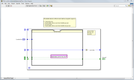
Figure 2 - Waiting for Bubble Event
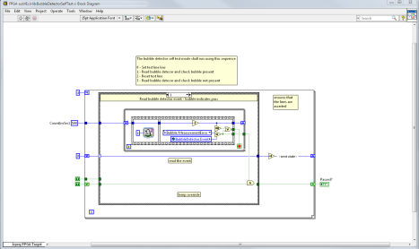
Figure 3 - Setting Self-Test Complete
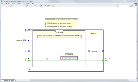
Figure 4 - Waiting for No Bubble Detection After Self-Test
True Parallel PWM Measurement
PWM measurement of the 1,000 Hz signal from the ABD07 Bubble Detector is performed by utilizing a Single Cycle Timed Loop running at the standard hardware clock rate of 40MHz. This PWM measurement loop is performed in parallel with the logic monitoring loop that latches the Bubble Event. Accordingly the BubbleDetectorMeasurementLoop.vi is set up to synchronize to the incoming signal by resetting counts on the Rising Edge of the incoming signal. The first measurements of On/Off counts are discarded. Each iteration tracks if the digital input signal is high or low. If the signal is high and it is not a rising edge event then both the Cycle Time and On Time counts are incremented and saved into FPGA VI Scope Register items. If the signal is low then only the Cycle Time count is incremented. On every High and Rising Edge detection after the initial detection, the On and Cycle Time counts are pulled from the registers and analyzed for duty cycle of the incoming signal. At 40 MHz a 1000 Hz signal cycle will last 40,000 clock ticks. Figures 5, 6, and 7 show the custom counter implementation.
Figure 5 - Rising Edge Cycle Start Detection
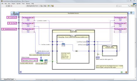

Figure 6 - Low Signal, Increment Cycle Counter

Figure 7 - No Rising Edge, Increment High Counter
The technical specifications for the Sonotec SONOCHECK ABD07 indicate the following output PWM range duty cycles. Measurements were found to have imperfect periods being output by the Sonotec SONOCHECK so the code ranges were spread to allow for 1 percent variation downward from the nominal minimums and the upper ranges of the measurement were set to be adjacent to the next measurement range (nominal minimum – 1 percent) to have no gaps in count coverage.
|
Bubble Size |
Duty Cycle |
Nominal Clock Ticks |
Clock Tick Tolerance Ranges |
|
No Bubble |
20% |
8000 |
7920 – 8315 |
|
Small Bubble |
21-79% |
8400-31600 |
8316 – 31679 |
|
Bubble |
80% |
32000 |
31680-35639 |
|
Device Fault |
90%+ |
36000 |
35640 |
Table 1 - Bubble Detector PWM Output Ranges
Figure 8 shows the code that calculates the Bubble Detection event based on the High clock ticks and the total Cycle Count Clock ticks based on the logic listed in Table 1.

Figure 8 - Bubble Event PWM Clock Tick Calculation
Rapid Prototyping Benefits of LabVIEW FPGA
The use of the FPGA on the sbRIO-9626 benefited this project by allowing prototyping of code and rapid testing of code interacting with hardware. No custom ASIC hardware was needed to achieve integration of PWM signal measurements. Custom counters were easily implemented as well as custom cycle start detection by incoming signal riding edge detection. The speed of the detection of the bubble events with the FPGA Single Cycle Timed Loop was a single sensor detection output signal PWM cycle. This meant bubble detection within 1 millisecond on the FPGA hardware!
An added benefit of utilizing the LabVIEW Development Environment with the sbRIO-9626 for measuring the PWM signal from the ABD07 SONOCHECK Bubble Detector was the ability to create test LabVIEW FPGA bitfiles for only the Bubble Detector code. This allowed rapid testing with FPGA Front Panel Interactive Communication mode and greatly shortened the time needed to hone the PWM measurement code to account for unspecified signal jitter from the ABD07 output.
Conclusion
LabVIEW FPGA and LabVIEW Real-Time and LabVIEW for Windows allowed DSA to easily meet the customer requirements for interacting with the Sonotec SONOCHECK ABD07 bubble detector sensor. Using LabVIEW also allows for easy transfer of this code to other projects utilizing an ADB07 bubble sensor in the hardware implementation. These bubble sensors are also used in Dialysis and transfusion machines, heart-lung machines, blood separators, infusion and cardiac pumps, nutrition pumps, and contrast medium pumps.
Contact Information
Ryan W. Vallieu, info@DSAutomation.com
Data Science Automation, 375 Valley Brook Road, McMurray, PA 15317-3370
Industry:
Advanced Manufacturing and Control Advanced ResearchAttributions:
Ryan W. Vallieu, Senior Automation Systems Architect, Data Science Automation, Inc.
Michael R. Brueggman, Chief Operating Officer, Data Science Automation, Inc.
Products Used:
sbRIO-9626
LabVIEW 2012
LabVIEW FPGA 2012
LabVIEW RT 2012
NI-RIO 12
Self-Qualification Form
As a technical user, you may know exactly what you need from us already. If you do, save time and streamline the discovery process with our self-qualification form, where you can let DSA know exactly what you need.
