
Immune Adsorption System for Cancer Treatment
The Challenge
Performing extracorporeal blood treatment on human patients while complying with European Union regulations for medical devices. The treatment system includes multiple patient protection measures which must be managed deterministically.
The Solution
Patient risks were minimized by using a single board RIO to manage the system with critical functions being handled by a deterministic real-time loop and the FPGA. These features allowed for deterministic system health checks and complied with the client’s risk assessment.
Introduction
Data Science Automation (DSA) is a premier National Instruments (NI) Alliance Partner that specializes in automating and educating the world leading companies. Clients choose DSA because of DSA’s deep knowledge of National Instruments products, disciplined process of developing adaptive project solutions, staff of skilled Certified LabVIEW Architects and Certified Professional Instructors, and unique focus on empowerment through education and co-development.
It’s Not Every Day You Get to Work on a Cancer Treatment!
Immunotherapy is a rapidly developing area of cancer treatment and provides an alternative to patients that are untreatable by traditional methods. There are a variety of immunotherapy techniques but what they have in common is that each attempts to modify the human immune system in ways that allow it to combat cancer cells. While this treatment offers an alternative to individuals who can tolerate traditional treatments but whose cancers cannot be targeted, it is a much bigger game-changer for the millions of individuals who cannot tolerate chemotherapy. In fact, many of the inhabitants of sub-equatorial regions carry many more parasites in their blood than in other regions, and chemotherapy is not an option for them because it simply allows the parasites to take over.
Our client is developing a system that performs extracorporeal treatment on blood, which means that blood is removed from a patient, treated outside of the body, and returned to the patient. This particular method of immunotherapy is designed to remove certain molecules generated by cancer cells that actually suppress the body’s own immune response to those cells. By releasing these molecules, cancer cells essentially protect themselves.
Removing these molecules requires very specific chemical reactions produced while sending the blood through a biologically engineered agent. Even though the rest of the system components are comparatively inexpensive and typical to medical devices, the cost of the biologic component makes the overall treatment expensive. So far, the technology has only been available to those able to afford it and in cases where the cancer is untreatable by traditional methods. There have been some success stories, but too few to reach conclusions on the average effectiveness of the treatment. Expanding this type of technology requires clinical trials, and for these to be affordable the treatment must qualify to be supplemented by medical insurance. For both of these reasons, our client is designing a production unit, requiring hardware and software design teams.
Working on Cancer Treatments Requires a Lot of Regulatory Compliance! Our client’s system is connected to a patient and fluid supply bags. Blood is circulated through a tubing set and treatment components via motor-driven pumps. The direction and path of flow is controlled by the pump direction and pinch clamps. At certain points the tubing passes through pressure sensors, a bubble detector, and a hemoglobin sensor, all to monitor for conditions that could damage the blood and threaten patient safety (Figure 1). The software is required to control the motors and pinch clamps, and log data from the pressure sensors, bubble detector, hemoglobin sensor, and load cells which monitor the volume of fluid supply bags. The software must also stop flow and close the clamps when an abnormal condition (hereafter referred to as a “fault”) is sensed. The software interface must enable the user to switch between several flow configurations that correspond to performing treatment, priming for treatment, pausing, etc.
These functions alone constitute a fairly generic flow control system. But, to preserve patient safety and comply with medical device regulations, this system requires deterministic responses to faults, as well as the highest possible level of system health and error monitoring. Our client’s initial system design – which involved a Windows-based touch-panel PC and USB-based DAQ - was not adequate to meet these requirements, so a number of options were considered: 1) Adding hardware fail safes for every condition that threatens patient safety; 2) Using a real-time OS for critical tasks in conjunction with Windows; 3) Utilizing a sbRIO to handle critical tasks while using the touch-panel PC for user interaction (Figure 2).
Medical devices have of course classically been hardware-centric, and have increasingly incorporated software as the reliability of software platforms has matured. Solid-state circuitry is still preferred because of its traceability, that is, because the path from design to product can be clearly traced. Software is still considered less traceable. For example, even in the case of an FPGA, it must be demonstrated that source code is compiled identically every time for maximum traceability. Since this is often not possible to demonstrate with software, additional measures must be taken to mitigate the risk. Still, in the case of our customer’s device, the hardware only option was rejected because it offered the least flexibility in design. The development path for this product included multiple cycles of system modifications in response to clinical feedback, which would have been nearly impossible if using solid state circuitry only. Real-time software updates offered a much more rapid and cost effective method of modification than hardware changes.
A sbRIO was chosen over a real time OS because of the maturity of the technology, DSA’s familiarity with NI RIO products, and as the best option for patient safety. This decision was made despite the cost added to the product, mitigated somewhat by the OEM availability of sbRIO products and the likelihood that, despite lower cost, alternate real-time solutions would have incurred higher development costs. The high reliability of FPGA (in addition to the determinism of the real-time software) also contributed to judgment that a sbRIO would be most likely to assure regulatory compliance and maximize patient safety.
Multiple Targets to Target Multiple Risks
The system software resides on three targets: the FPGA, the RIO, and the touch-panel PC (hereafter referred to as the HMI). The RT code manages the main functions of the system. The FPGA code handles the majority of the hardware interactions and critical patient safety functions. The HMI code is reserved for only the least critical functions and user interaction. This architecture fits well with the system’s paradigm for patient safety and regulatory compliance. To minimize patient risk, responses to faults must take place in the most reliable manner possible. Therefore, responses at the hardware level (i.e., via solid-state circuitry) are preferred. On the software level, the FPGA is considered the most reliable target, and the HMI the least reliable, with the RT in the middle. The RT code is further divided into deterministic code (more reliable) and non-deterministic code (less reliable).
Following this paradigm, the system is configured to enter a safe state when power is removed. The depowered state of the clamps is closed, and of course when power is removed the pumps stop also. Under those conditions all flow is stopped. The FPGA provides a heartbeat on a digital line high which is monitored by the system’s solid-state circuitry. If the heartbeat stops then the pumps stop and the clamps close.
The majority of hardware interactions are handled by the FPGA code, and wherever possible the internal logic of the FPGA is used to detect faults and immediately stop all flow. For example, system pressures are monitored and flow is stopped if any pressure limits are exceeded. One exception to this is motor control: there is a limited selection of pumps certified for medical use and the ones selected for this system use serial control which must be performed by the RT code. However, there is also a digital override to this serial control. The line is held high by the FPGA, and if any faults occur it can be sent low to override serial control and halt the pumps. Faults that do not originate in the FPGA code (from the RT or HMI) are relayed to the FPGA from the RT code.
The RT code contains the majority of the systems functions including a central state machine. Data is exchanged with the FPGA via DMA’s and the FPGA front panel. This includes RT drivers for each piece of hardware that obtain raw data via the FPGA. The FPGA and RT also monitor each other’s health via watchdog signals. The RT code includes a deterministic loop whose primary purposes are fault
monitoring and data collection. This gives high priority to any faults that are detected at the RT level or received from elsewhere, so that they can be relayed to the FPGA without delay. It also monitors the FPGA for FPGA-level faults, so that mitigating action can be taken on the RT level (changing to a safe state and informing the user via the HMI, and resetting faults on the FPGA after user intervention). The remainder of the RT code including the central state machine are non deterministic. Finally, the HMI code handles user interaction and other low-priority tasks such as logging system data to a database.
The Payoff
The system is currently being delivered after approximately 16 two-week development cycles. In each of those cycles certain sets of functionality were delivered to the customer and clinical feedback was provided, so that corrections could be made in the following cycle in addition to adding new sets of functionality. The design paradigm allowed multiple developers to work on the software simultaneously: at least 1 developer on both the FPGA and HMI source code, and at least 2 developers on the RT code (separating the state machine and other non-deterministic functions from the deterministic code). This still required collaboration to maintain communication between each software component as the design changed, but the ability of a multi-developer team to deliver incremental functional designs in two-week cycles allowed DSA to respond to the customer’s aggressive delivery schedule.
Contact Information
Paul R. Tortora, Ph.D., prt@DSAutomation.com
Data Science Automation Inc., 375 Valley Brook Road, Suite 106, McMurray PA 15317 (724)942-6330
Figure 1: Main Physical System Components
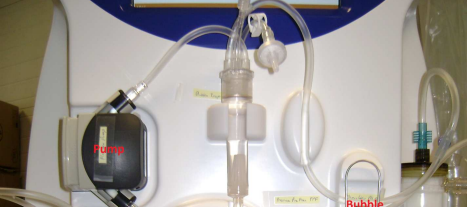
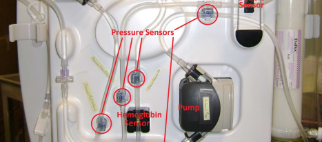
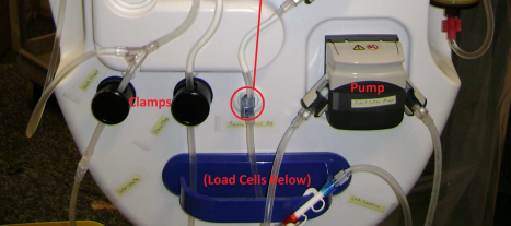

Figure 2: Main Software System Components
Industry:
Advanced Research Machine ControlAttributions:
Paul R. Tortora, Ph.D., Senior Automation Systems Engineer, Data Science Automation, Inc.
Timothy D. Nolan, Senior Automation Systems Consultant, Data Science Automation, Inc.
Products Used:
sbRIO-9636
LabVIEW 2012 SP1
TestStand 2012
Self-Qualification Form
As a technical user, you may know exactly what you need from us already. If you do, save time and streamline the discovery process with our self-qualification form, where you can let DSA know exactly what you need.
