
FPGA Step and Direction Control of Motors with Ramping
The Challenge
Perform hardware controlled Step and Direction output on 3 stepper motors with ramping to velocity set point targets while also validating encoder input feedback based on step output counts.
The Solution
The sbRIO-9626 FPGA is used to perform SPI communication to the Stepper Drive boards for setting the drive currents as well as for outputting the Step and Direction signals for the three motors.
Introduction
Data Science Automation (DSA) is a premier National Instruments (NI) Alliance Partner that specializes in automating and educating the world leading companies. Clients choose DSA because of DSA’s deep knowledge of National Instruments products, disciplined process of developing adaptive project solutions, staff of skilled Certified LabVIEW Architects and Certified Professional Instructors, and unique focus on empowerment through education and co-development.
A biomedical device needed to have hardware level control of motion control outputs to stepper motors driving fluid pump heads. Software of Unknown Provenance (SOUP) where documentation could not be easily obtained was a deciding factor in moving away from the original intelligent stepper motors used in a prototype system that performed the same functionality. FMEA indicated that the motor control should be implemented on the FPGA for highest reliability and safety intervention.
The ability to implement custom communication protocols on the FPGA for SPI communication to the stepper drives was an important driver in selecting to control the motors from the FPGA. The motor drive settings are basically only set to 2 levels of power – either low current settings when the motors are not commanded to move or full available current when the motors are commanded to start moving. SPI communication is validated with the query of any parameters that are changed. If the query does not show the same value that was sent to the drive the system is put into safe mode (no motor power) and fluid motion is blocked by solenoid driven clamps.
Direction settings are easily maintained to the motor drivers. Only one motor is allowed to change directions during a tube priming phase of operation. The other two pumps are never allowed to change direction and have the direction bit hard coded into the FPGA as constant values to output on the Step and Direction lines to the motor drives.
Set points are sent from the HMI software to the Real-time executable and the RT code interacts with the FPGA for target RPM set points via front panel programmatic communication. Set points are validated against checksums to prevent corruption of communication between the RT system and the FPGA code.
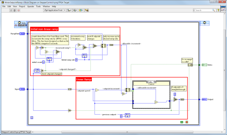
RPM set points are converted to a number of clock ticks that must elapse between step outputs. The step generation code is running in a Single Cycle Timed Loop on the FPGA and the clock ticks are counted to know when the steps should be generated. Set points are sent to the motor step output clocking loop in a ramp so that the maximum RPM is not set immediately on receiving a new set point. A memory item is used to transmit the RPM clock cycle set points to the Step Generation code from the 10-ms cycle clock cycle target generation loop, MotorControlSetpointGeneratorLoop.vi (Figure 1). This is to allow for smooth ramping. Two part ramping (Figure 2) is implemented where an initial 6- point non-linear ramp is implemented and then transitions to a linear ramp until the target clock ticks (RPM) is achieved.
Figure 1 - RPM Conversion to Clock Cycle - Ramped Targets
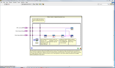
Figure 2 – Set Point Ramping Control
While the system is performing Step outputs the quadrature encoder inputs are validated against the tracked Step output counts to ensure that the motor is not stalling or falling behind the commanded motion. A known number of quadrature cycles of the 400 CPR encoders allows for checking for the proper number of encoder feedback counts per twelve output Step signals. The system in parallel with the Step output generation is decoding the Quadrature Encoder signals on the A and B channels (Figure 3 and Figure 4).
Figure 3 - Motor Control Output Loop and Speed Check
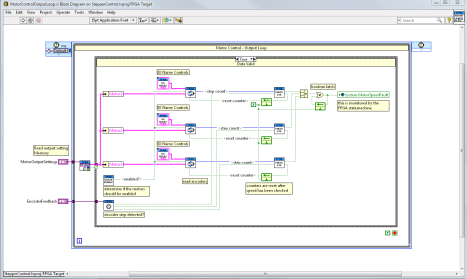
Figure 4 - Motor Encoder Feedback
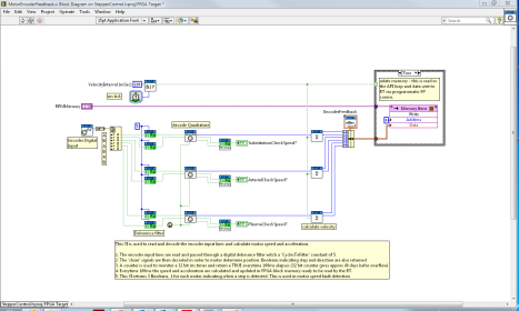
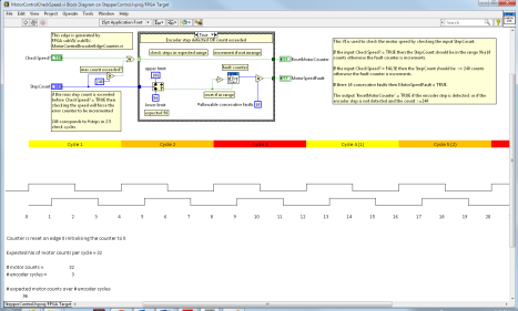
In this system with 400 Counts per Revolution (CPR) quadrature encoders there are 12 encoder edge counts expected with 3 encoder cycles since they are Quadrature encoders (1 encoder cycle is 4 edges) and x4 decoding is performed by MotorEncoderFeedbackDecodeEncoderPosition.vi. Once 12 same direction encoder edge detections have been detected the “CheckSpeed?” Output is set to true. A single encoder cycle is 32 motor output steps with the 12,800 step microstepped motors and a 400 CPR encoder. Thus the expected motor output steps for 3 encoder cycles (12 encoder edge counts) is 96 motor output steps (Figure 5). Speed mismatch is allowed up to 10 times before a system fault is triggered that shuts down the motor control and prevents fluid motion.
Figure 5 - Motor Control Check Speed
This final implementation satisfies the requirements for stall detection and smooth ramping. Other hardware options considered initially were intelligent controllers, however control from the Real-Time code did not meet the risk mitigation level required by the client and the certification team.
Rapid Prototyping Benefits of LabVIEW FPGA
The use of the FPGA on the sbRIO-9626 benefited this project by allowing prototyping of code and rapid testing of code interacting with the motion hardware. No custom ASIC hardware was needed to achieve integration of PWM step signal and quadrature encoder measurements. The speed of the encoder detection events with the FPGA Single Cycle Timed Loop was well above the maximum speed required of the system.
An added benefit of utilizing the LabVIEW Development Environment with the sbRIO-9626 for interfacing the Step outputs and Encoder signals was the ability to create test LabVIEW FPGA bitfiles for only the motion code. This allowed rapid testing with FPGA Front Panel Interactive Communication mode and greatly shortened the time needed to hone the motion code.
The LabVIEW environment also makes reuse of this code on other projects in the future very simple. As long as the FPGA IO Nodes are updated the code can be ported to multiple sbRIO and cRIO targets.
Conclusion
LabVIEW FPGA, LabVIEW Real-Time, and LabVIEW for Windows allowed DSA to easily meet the customer requirements for providing hardware level control and speed monitoring of three separate stepper motors in a biomedical device. Using LabVIEW also allows for easy transfer of this code to other projects utilizing stepper motors with or without speed feedback verification and SPI communication. The ease of writing modular code for the FPGA carrying over modular coding techniques allows for this ease of code transfers between projects.
Contact Information
Ryan W. Vallieu, info@DSAutomation.com
Data Science Automation, 375 Valley Brook Road, McMurray, PA 15317-3370
Industry:
Advanced Manufacturing and Control Advanced ResearchAttributions:
Ryan W. Vallieu, Senior Automation Systems Architect, Data Science Automation, Inc.
Richard M. Brueggman, Founder and CEO, Data Science Automation, Inc.
Products Used:
NI sbRIO-9626
LabVIEW FPGA 2012
LabVIEW RT 2012
LabVIEW 2012 SP1
NI RIO 12.1
Self-Qualification Form
As a technical user, you may know exactly what you need from us already. If you do, save time and streamline the discovery process with our self-qualification form, where you can let DSA know exactly what you need.
