
Gas Well Fracturing Proppant Delivery System
The Challenge
The Client needed to have an acquisition and control system to monitor and control the amount of propant material being pumped into a well being fractured. This system also needed to be calibrated and control liquid additives and dry additives along with the flow rate of water.
The Solution
Using LabVIEW, Data Science Automation created an application that allowed the user to set the amounts of additives and the amount of proppant to the rate of water for fracturing the well.
Abstract
The client needed to have a system that a worker in the oilfield could operate to control the amount of materials that were being pumped in the well during hydraulic fracturing. The system needed to be calibrated when it was first installed and after any field sensor changes to ensure the correct amount of materials were pumped into the well. The system uses feedback control to make adjustments to the additives to maintain specified concentrations and flow rates.
Introduction
This hydraulic fracturing process was originally performed manually with multiple operators. One person would monitor the reading from one system then request the operator of the equipment to make process adjustments, then wait to see the result of the changes and iterate. With the new system in place the desired output setpoints are set by one operator and the system controls several pieces of equipment and provides instant feedback.
The first step in the process of automatic control is to select the proppant truck that you wish to control. If the truck has not been calibrated the operator must perform a calibration on the channel pairs that are to be used to control the feedback. In Figure 1 you can see the output channel and its corresponding feedback channel. Once the allowed channels are calibrated they are saved on a template on the Compact FieldPoint (cFP) embedded controller so that the future operators do not need to repeat this step. A user can use the calibration panel to manually control the output and watch the input values respond as they plot the data points. The calibration is broken up into several quadrants to ensure that the calibration is distributed over the range of the signal. The calibration screen is also where the operator will set up the time and percent of target information for the channel they are working with. This allow the automation to quickly ramp up to a value close to the target then hone in on the desired value and hold the output until it needs corrected.
.png?width=431&height=303&name=unnamed%20(59).png)
Figure 1–This is the calibration screen that allows the operator to calibrate and save the settings to the cFP. This allows a calibration to be used by future users without the need to recalibrate each time it is used.
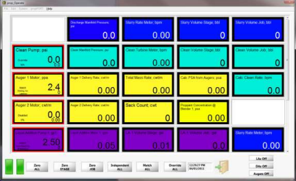
The next step in the process is to select the signals that the operator would like to have displayed on the main application user interface. This is done by selecting the blocks on the screen shown in Figure 2 and choosing the value that is desired to be seen. By choosing the blocks in this manner the operator can set up a display that is custom to the specific needs of the job. Once the operator has set up the display it can be saved to a file for future use on other jobs that are similar. Likewise, the operator my load a saved configuration template from a file and use it to run the job. Each information block represents a channel that was created to display data. Some of the channels viewed in the screen are calculated from one or more input channels and others show the target value and the real-time value in the same block so the operator can see if any adjustments need to be made. On the bottom of the screen the operator has controls to allow the zeroing of totals for the entire job or just the current stage of the job that is running. The operator can also control the automatic operation of the application by the use of additional controls. The “Independednt ALL” button allows the operator to use feedback for the individual channel but not link them to the master rate feedback, The “Match ALL” button uses the feedback to match to the output rate, and the “Override ALL” allows the operator to manually set the output based only on the calibration curve. The operator also has the option of turning off the liquid additives (LA), dry additives (DA), and the augers that are adding the proppant through three additional buttons on the operator screen.
Figure 2–This screen is the operate screen that allows the operator to set up and display the data that is desired for the job.
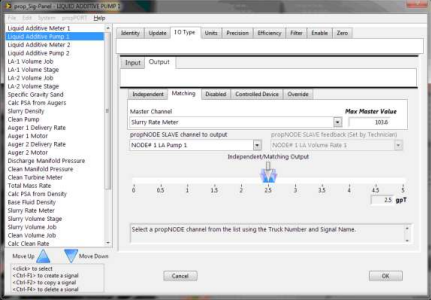
The blocks on the operator screen can be clicked to set the desired channel and make modifications to the signal information that is being displayed. By clicking a channel block the signal panel (Figure 3) will appear and allow the operator to make changes to that channel or others by selecting them on the left hand side of the window. From the signal panel the operator may change many characteristics of a channel. This is where the operator may set the output value of a channel and if it will be independent, matching, disabled, a controlled device, or in override. The pairing of channels can only be done in the calibration screen to avoid selection of uncalibrated channels. Figure 3 shows a channel that has been calibrated and is being matched to the slurry rate meter. The slide control allows the operator to set the rate desired (large arrow slider) and the window of allowable drift (two smaller arrow sliders) . The operator could also change the operation of the channel to independent or override. Once the operator has completed changes and clicks the OK button it will return them to the operate screen and save all of the changes made. If the operator does not want to accept the changes made they can simply click the Cancel button to discard the changes and return to the operator screen.
Figure 3 – This is the signal panel that will allow the operator to set output and change signal parameters to customize the job information.
Summary
A flexible configurable system was created to control the amount of proppant and additives being pumped downhole during multi-stage hydraulic fracturing to stimulate production. The system frees operators to focus on safety critical aspects of the process and results in a higher level of consistency and reliability.
Industry:
Embedded MonitoringAttributions:
Bradley J. Westfall
Consultant, Measurement & Automation
and
Ronald J. Cochran
Senior Engineer, Measurement & Automation
Data Science Automation, Inc.
USA
Products Used:
LabVIEW 2009
cFP 2120
cFP AI 111
cFP AO 210
cFP CB-1
cFP four slot back plane
Self-Qualification Form
As a technical user, you may know exactly what you need from us already. If you do, save time and streamline the discovery process with our self-qualification form, where you can let DSA know exactly what you need.
