


Figure 1 Many applications require communications across multiple platforms.
This Nugget discusses a classic method that is seldom mentioned.
Two of the powerful features of an AE are that they provide both encapsulation and protection for the data stored in them. These features are not limited to a single application instance or a single machine. Utilizing a seldom used feature of LabVIEW (LV) your AE’s can expose the functionality of one or more AE’s to other applications or other machines with limited effort on the part of the developer. This approach will be shown in an application where I harnessed these strengths to deliver a multi-node application. I will first outline the challenge and then walk through the implementation.
Challenge:
Allow a user of a Windows based LV application to control and monitor the internal state of an FPGA controlling a motor.
Solution:
Use VI Server to serve an Action Engine running on RT node to the Windows based application.
Discussion:
VI Server has been available since version 5 of LV. VI Server is the service used to create background processes using the Invoke Node method “Run VI” (see figure 2 below). Typical usage involves first opening a reference to the target VI, setting controls (using Invoke Node >>> Ctrl Val.Set) and then run the VI (see the example included in this Nugget for an example of this approach).
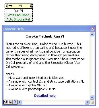
Figure 2 Invoke Node >>> Run VI allows us to run a VI that can be determined at run time.
While invoking dynamic VI’s to run in the background using the Run VI method (see figure 2) is common in many applications, but is not limited to the current process context, nor is it limited to the machine the LV code is currently running. VI Server supports and allows connections from other contexts or from other machines on the network. This is accomplished by using an often un-wired input to the “Open VI Reference” node. But before I dive into the details I would like to first introduce the “Actors” in our play.
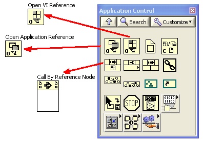
Figure 3 The Application Control palette contains
the functions we need to use cross-platform AE’s.
The “Actors”
Implementing cross-platform capable AE’s requires three functions found on the “Application Control” palette. The three functions are (see figure 3):
- Open VI Reference
- Open Application Reference
- Call by Reference
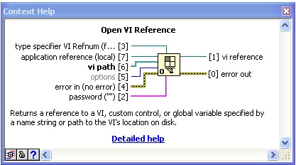
Figure 4 Open VI reference allows you to specify the application instance.
The Open VI Reference node has only one “required” input, the “vi path”. The “vi path” input is generally used to specify the VI name if the target VI is already loaded in memory or the complete path to the target VI when it is used to prepare a VI to run as a background thread. But as shown in Figure 4 above, there are inputs that let us specify the application in which the VI will be opened as well as being able to specify the type specifier of the target VI (more on this later in this Nugget). One particular interest in the context of Cross-platform AE’s is the “application reference”. The “application reference” can be obtained using the “Open Application Reference”.
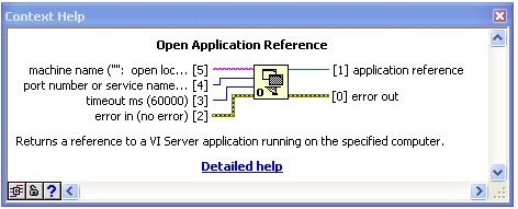
Figure 5 Open Application Reference gives us access
to VI’s running in other contexts, or other machines.
While launching background processes we do not have to use the “Open Application Reference” (OAR) node to obtain a reference to the target application instance because LV will default to the current instance. This is very convenient for background threads, but can result in us over looking functionality that can be very useful. When properly configured and used the OAR will let us “reach out and touch VIs” running inside other executables on the same machine the code is running on, or applications running on other nodes. We can execute Vis on other nodes as if they where on the same machine.
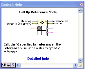
Figure 6 Call by reference node passes inputs to
and executes the target VI then retrieves the results.
The third critical function required to facilitate using cross-platform AE’s is the “Call By Reference” (CBR) node (see figure 6). The CBR allows us to develop code that can call VIs based on run-time conditions. They can be viewed as sitting somewhere between a Polymorphic VI (where the target VI is determined at development time) and LVOOP, where the icon layout is restricted to allow the target VI to be determined and called at run-time. Therefore, the Call By Reference node can be viewed as both flexible and restrictive. It is restrictive in that it will only work with Vis that have an icon layout the CBR is configured to use but flexible in that provided the target VI has the right icon connector it can work with any VI, anywhere (provided there is a network connection available).
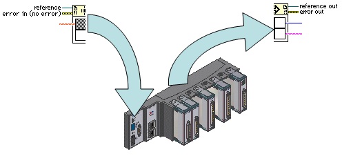
Figure 7 A conceptual drawing illustrating how a Call By Reference node functions.
Figure 7 shows a conceptual drawing of a CBR node being used to invoke a VI on a RT target. The CBR can be viewed as being cut in half; splitting the input terminals from the output terminals. When called the inputs are passed over the network connection to the node with the target VI. The target VI is invoked on the RT node and when the target VI completes, the returned data is passed back over the network where the results are returned as if the target VI resided on the local machine.
The Plot
Before diving into the blow-by-blow action carried out by our “Actors” we should first examine the scene where they each play their role. For the purposes of this Nugget, I will use an application that was designed to control and monitor the performance of a motor sub-system controlled by an FPGA. The high-level design is shown in figure 8 below.
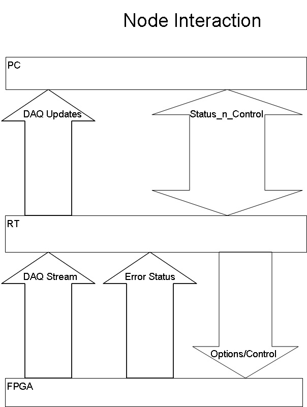
Figure 8 Interactions between elements of the system.
The PC running a Windows based LV application will monitor logging and status updates and keep the GUI updated as well as providing logging to disk functions. The RT node acts an intermediary between the Windows application and the FPGA. The FPGA performs all the Time-critical tasks while passing status and performance updates to the RT, which will buffer updates until requested by the Windows application. While the application we will examine is very specific and focused on the motor sub-system, it utilizes techniques that can be readily adapted for other situation where an application on one machines needs to gather information from another.
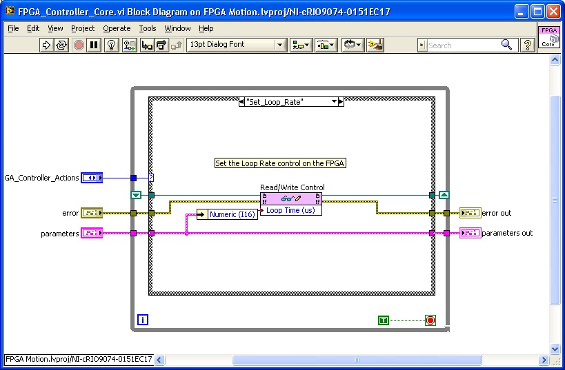
Figure 9 Read/Write Control nodes allow control of FPGA from the RT node.
Controlling the FPGA from the RT Node “The Fly in the Ointment”
The control of the FPGA from the RT node is supported using “Read/Write Control” method (see figure 9) node. Readers should consult the NI documentation for more information about how the “Read/Write Control” (RWC) method is implemented if interested. For the sake of this Nugget the important detail to note is the RWC requires a valid “FPGA VI Reference” to operate. The operative word in that sentence is “valid”. Use of the RWC is restricted to the application instance where it was opened. In the case above, using the RWC can only be executed on the RT node “the fly in the ointment”.
The FPGA VI reference is required everywhere the RWC is used. This can be accomplished by wiring the FPGA VI reference into all VIs that need to act on the FPGA using a RWC or the FPGA VI Reference can be recognized as being a shared resource and wrap-up all of the FGPA control functions as various “Actions” (alternatively called “methods”) of an Action Engine.
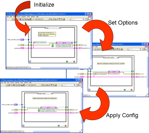
Figure 10 The FGPA_Controller_Core (an AE) call
sequence to initialize, configure and apply settings.
The Principle Actor – FPGA_Controller_Core
The “FPGA_Controller_Core.vi” (“FCC” see figure 10) will be our principle actor appearing in all scenarios where we need to interact with the FPGA. As portrayed in figure 10, the FCC is first initialized with the caller specifying the FPGA VI reference. The specified reference is used to first disable the application of configuration settings (application specific operation) and place the FPGA in a Configuration Mode where it will accept new run-time settings (yet another application specific operation). The FPGA VI Reference is finally cached in a Shift Register to be used when required.
After placing the FPGA VI reference in the Shift Register, we can use the Read/Write Control node to act on any of the FPGA controls. This ability is illustrated in the “Set Options” step shown in figure 10 where the FGPA VI reference is used to establish setting used by the NI 9514 (Servo Interface) and again where the “Apply Config” portion of Figure 10 shows the “App Configuration Settings” Boolean is set true and the “Enable Configuration Mode” is set false.
Using this architecture any of the FPGA settings can be manipulated using the FPGA_Controller_Core. Utilizing the function introduced earlier, we can “Reach Out and Touch” the FPGA from outside the RT context.
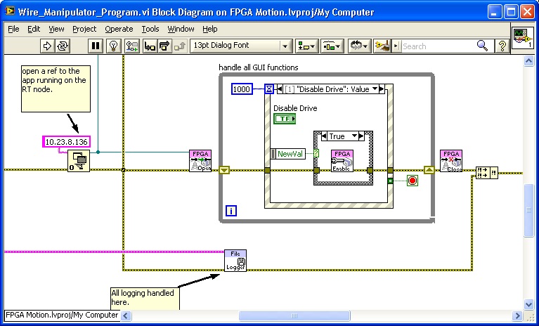
Figure 11 shows a portion of the Block Diagram of the application
running on the Windows platform. A reference is opened to the RT node.
Setting the Scene
With the actors and the plot defined it’s now time to set the scene. The show opens with a string containing the IP address of the RT node being passed to the “Open Application Reference” (see figure 11). After locating the remote node and verifying the node will accept VI Server sessions a reference is returned that can be used to access elements in the target process context. Please note the Application Reference wire branches to allow parallel tasks to be performed on the target node. The upward branch is used for logging and I will touch on that latter in this document. For the sake of the current narrative, please observe that the Application reference is passed to the sub-VI “FPGA Open” (Actual name is “Open_Connection.vi”).
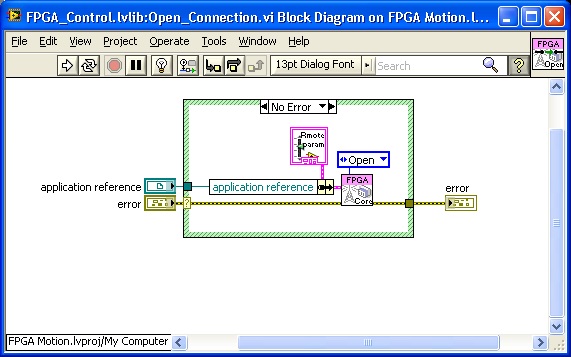
Figure 12 Block diagram of the wrapper that opens a connection to a VI on the RT node.
Taking a quick look inside of the “Open_Connection.vi” (see figure 12) we discover it is a wrapper around another Action Engine and we are invoking a method (action) called Open and passing the Application Reference using a cluster. Before digging into the Action Engine, I would like to call attention to the form of the AE. All of the parameters passed to the AE are passed using a cluster with the required parameters being passed by the caller using required inputs. By creating a “wrapper” for each AE method you can ensure that other developers using your Action Engines are using them correctly. In addition to ensuring your Action Engines are being used correctly you can easily locate where a specific Action Engine method is being used by search for the wrapper for that method. Another advantage of using Action Engine Wrappers is that the Action Engine, and all of its wrappers, can be placed in a LVLIB where you can mark the Wrappers as public scope and the Action Engine itself as private. Continuing our search into the Action Engine we find one of the supporting actors in the Open Case.
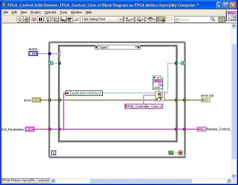
Figure 13 The Open VI reference node allows us to
open a reference to the VI “FPGA_Controller_Core”
Examining the Open case of the “Remote_FPGA_Controller-Core.vi” (see figure 13) we see the Application Reference is unbundled and passed to the Open VI reference node. The two other values passed to the Open VI reference node are the name of the target VI (FPGA_Controller_Core.vi) and the type specifier. The type specifier is used when the Open VI reference executes to ensure the target VI is compatible with the specifier. If the target does not have compatible icon connector an error will be returned. The specifier also determines the nature of the VI reference as we will see later. The returned reference is cached in the Shift Register (SR) of the AE.
Before we run through the rest of the show I should stop and point out a subtle distinction between the two Action Engines we have examined. The code shown in Figure 13 is named “Remote_FPGA_Controller.vi” while the AE we saw in figure 10 is named “FPGA_Controller_Core.vi”. The former has a reference to the latter and the latter has a reference to the FPGA. The “Remote” version uses an antenna in its icon.
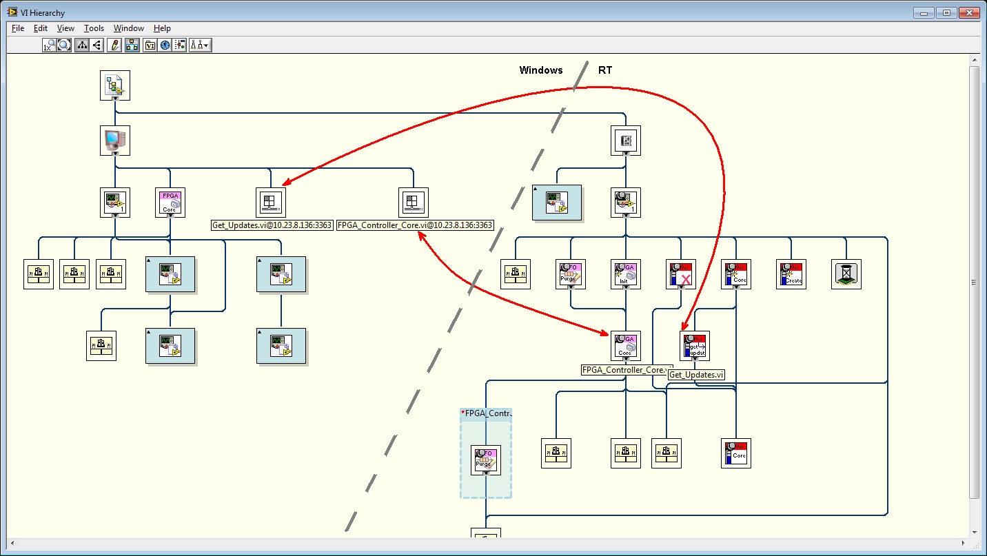
Figure 14 shows the application hierarchy and how the Windows and RT nodes interact.
Moving to the Balcony for Another View
Figure 14 gives us a high-level view of the interacting elements. Libraries not involved in this discussion where minimized so we can focus on the parts that play a role in the communications. The left side of Figure 14 shows the VIs running on the Windows platform while the right side shows the RT side. There are two connections shown, one for the status and control of the FPGA and the other is used for high-speed logging updates. We will focus on the Control and Status code. Readers should take special note of the two icons that appear to be black and white versions of the Open VI reference node. Their appearance is not an accident because they represent the connection to the target VIs. Every time an Open VI Reference node successfully opens a target VI an icon representing this connection is added to the hierarchy screen. This gives us a method to quickly check if the connection attempts were successful. The other detail that should be noted is the name of the icon reflects not only the name of the target VI but also the IP address of the node. Again, this is helpful when we are working with multiple nodes. I have also added red lines to indicate which VI on the RT node is accessed by each VI reference.
Notes:
Ctrl-a with the Hierarchy screen open will show all VIs in memory.
The blue boxes with generic LV icons are collapsed libraries.
Summarizing:
Open Application reference let us point at the RT machine.
Open VI Reference let us point a VI in the target application.

Figure 15 shows the VI used to control and monitor the
FPGA from the Windows application (duplicate of fig. 11)
Let the Show Go On!
We previously observed that the Open Application reference lets us point at an instance of LV running on the RT node. The Application reference lets us open a reference to a VI inside that process context using an Open VI reference node and that the reference of the target VI was stored in the Shift Register inside the Remote “FPGA_Controller.vi”.
If we now shift our attention to the Event Structure shown in figure 15, we see a VI that appears similar to the Wrapper we used to open the connection to the target VI. When the “Disable Drive” button changes states the Value Changed event fires and the “NewVal” is used to select which wrapper we call.
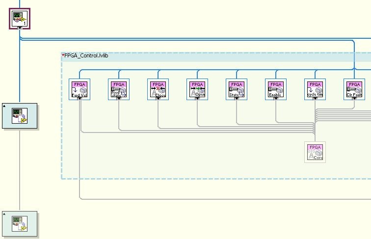
Figure 16 shows a portion of the VI hierarchy screen
that features the Remote_FPGA_Controller and callers.
The Plot Thickens
Examining the VI hierarchy (see figure 16) shows that the “Enable” VI we observed in Figure 15 is another wrapper around the Remote_FPGA_Controller that was initialized earlier. Digging into the “Enable” we find the same Action Engine being invoked using an “Enable Config” method. Examining the “Enable Config” case (see figure 17) inside the Remote_FPGA_Controller we find the third actor in our story, the “Call By Reference” node.
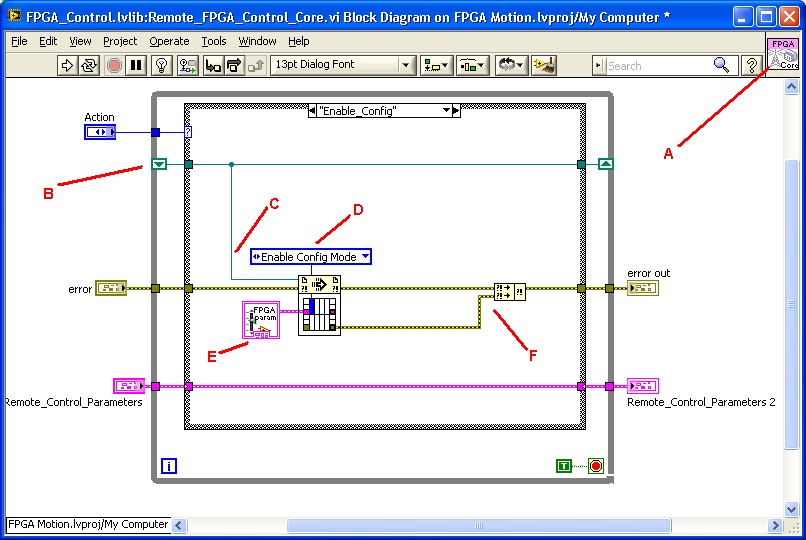
Figure 17 the “Enable Config” case uses a Call by
reference node to act on the VI running on the RT node.
Recreating the Crime
Figure 17 shows the Call by reference node being used to invoke the “Enable Config Mode” action of the FPGA_Controller.vi which is running on the RT node. While this VI exists in the application running on the Windows machine, only a portion of the execution is performed on the Windows machine. A short narrative outlining what happens when this VI executes follows a list of enumerated comments (see figure 17).
Antenna icon distinguishes this VI that runs on the Windows machine from the VI that executes on the RT node.
- The “Shared Resource” encapsulated by this AE is a strict VI reference to the VI running on the RT node.
- The Strict VI reference defines the icon connector used by the Call By Reference Node.
- A type defined enum declaring the requested action is defined by the target VI on the RT node.
- This call requires no parameters but a type-defined cluster accommodates any used parameters.
- The two error clusters allow us to check for errors with the VI Server connection or errors when applying the setting to the FPGA from the RT node.
Narrative
The required and optional inputs as defined by the target VI are transferred using the UI thread to the VI Server process. The VI server service (not running in the UI thread) interacts with its complimentary service on the target machine to move the input parameters across the connection. The target VI is then invoked by the VI Server on the target machine using the parameters provided. After completion the returned values from the sub-VI call are transferred back to the requesting VI server and the UI thread is then used to transfer the results back to the Call By Reference node where the results are made available to the calling VI.
Benefits of using a cross platform AE
NO TCP code required.
Network connection is abstracted by VI Server. Listeners, polling, and connection health are all handled by VI Server. VI Server will not only transfer the data and call the target VI, it will also maintain Time Out status and check on calls that take a long time to ensure they are still progressing.
NO data conversions required.
The data type passed into and out of the Call By reference node is defined by the strict VI reference defining the inputs and outputs. There is no need to maintain code to convert non-flat data into a string and vise-versa. Any changes to the data used by the target VI are realized automatically as soon as the VI is updated. While this may break wires when a drastic change is made to the icon connector of the target VI, the need to modify the data structures is realized at development time. Data Parsing not required.
No Extra Loops
Since VI server is built into LV, we do not have to drop any extra loops on our diagrams to support the communications.
Easily expandable
If we need another connection, we simply open another target VI (See figure 14).
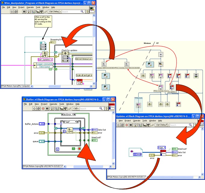
Figure 18 shows the code used to realize a cross-platform queue.
Extend functionality across machines
Queues are very useful entities when dealing with application that run at different rates. They are the prime component in design patterns like “Producer/Consumer” etc. However, Queues are only accessible using queue references which are only valid in the process context in which they we created. (Layman’s version: You can only use queues in the application where you created them). VI Server and Call By Reference node adhere to these restrictions but allow for cross-platform queues. Figure 18 illustrates one way of realizing a cross-platform queue.